Synchronized Square Wave Output

The event system can be used to produce a square wave synchronized to either the 3DM-CV7's internal reference time or an external timestamp. The square wave output can be used to trigger other devices at a consistent system-level time base.
For example, a PPS from a GNSS could be input into the 3DM-CV7 and a 100 Hz square wave could then be generated that is synchronized to the GNSS timing. This output could be used to drive a camera, thereby synchronizing the 3DM-CV7's data and the camera shutter with the GNSS timing signal.
In this example, we'll show you how to configure an interval trigger and GPIO action to produce a 60 Hz square wave synchronized to the 3DM-CV7's internal reference time.
Hardware Setup
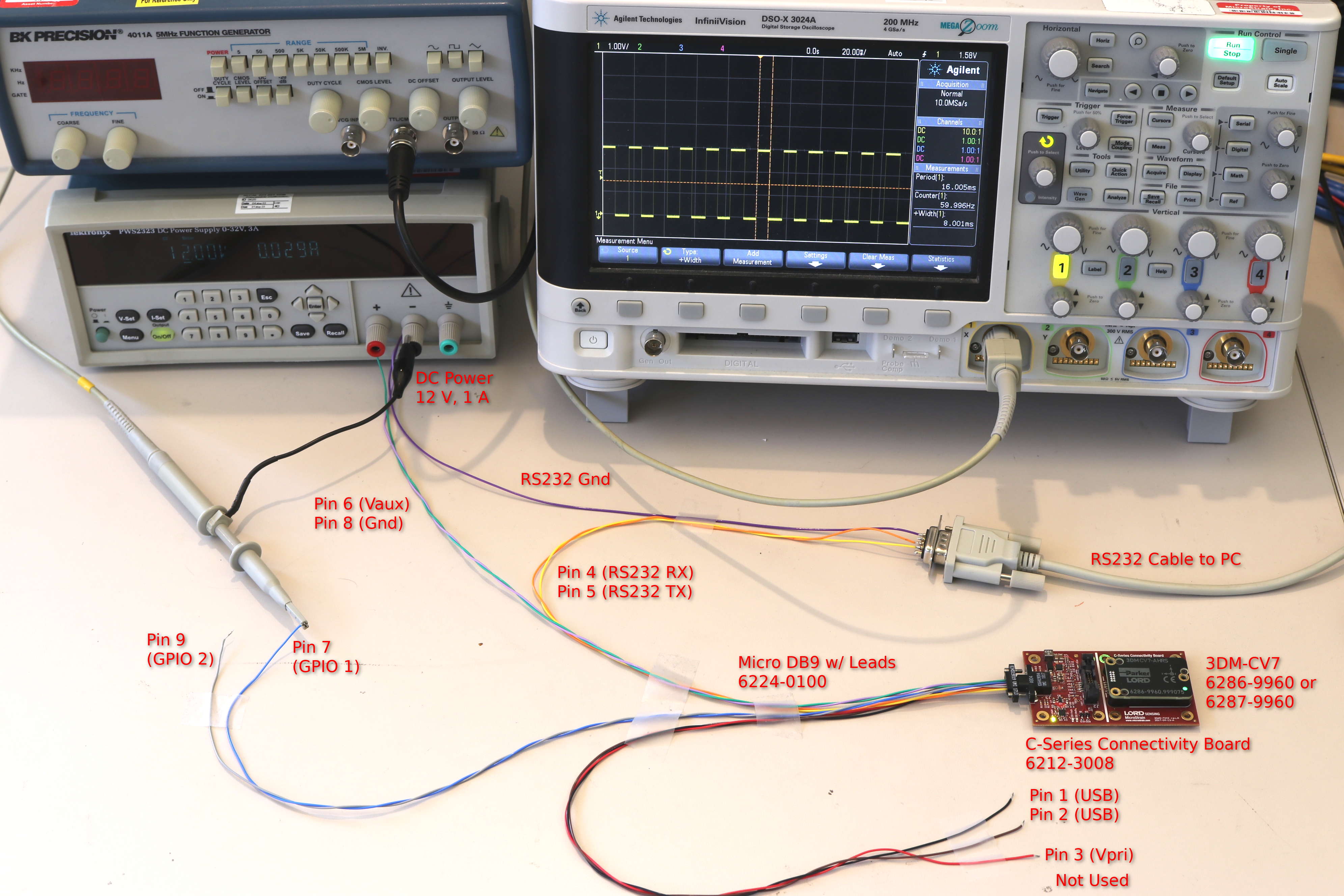
Connect an oscilloscope to GPIO 1. Set the time scale to 20 ms per division and the amplitude to 1 V per division with DC coupling. Set the trigger to rising edge, DC coupled, and a threshold of 1.5 V. Alternatively, a frequency counter can be used. Another option is to use an LED, logic probe, or multimeter, but the frequency will have to be reduced to a few Hz in order for it to be visible.
GPIO Setup
GPIO 1 must be configured using the GPIO Configuration (0x0C,0x41) command. Since we'll be using it with a GPIO Action, we must select the GPIO feature and one of the output modes (either high or low).
Command: GPIO Configuration (0x0C,0x41)
- Function: WRITE (0x01)
- Pin: 1
- Feature: GPIO (0x01)
- Behavior: GPIO_OUTPUT_LOW (0x02) (GPIO_OUTPUT_HIGH could also be used, then the pin will be high by default when the action is not configured yet)
- Mode: None (0x00)
Command bytes: 0101010200
MIP Packet: 75650c07 07410101010200 3a64
There should be no noticeable change on the oscilloscope or frequency counter except possibly a reduction in the noise level. The pin will read close to 0 volts because it's now configured to output low. If you instead configure it to OUTPUT_HIGH mode, the pin will read about 3 volts (unless a load such as an LED is connected, then it will read a lower voltage). This is a good way to check if your measurement is working. Which mode is selected does not matter for this example as it will be overridden by the event system.
Event Action Setup
Next, we'll configure an event action to control GPIO 1 using the Event Action Configuration (0x0C,0x2F) command. We want it to directly control the state of the pin, so we'll use the ACTIVE_HIGH mode. ACTIVE_LOW could also be used if the opposite polarity is desired.
- Function: WRITE (0x01)
- Instance: 1
- Trigger: 1 (we'll use this as the trigger ID below)
- Type: GPIO (0x01)
- Parameters:
- Pin: 1
- Mode: ACTIVE_HIGH (0x01)
Command bytes: 010101010101
MIP Packet: 75650c08 082f010101010101 2b31
Event Trigger Setup
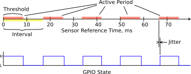
The final step is to configure an interval trigger. We'll set the data quantity to the Reference Timestamp (0xFF,0xD5) in the Sensor Data set. The interval will be the base rate divided by the frequency, or 1 kHz / 60 = 16.666667. For a 50% duty cycle, the threshold must be half of the interval, or 8.3333333. Note that since the trigger is updated once every event cycle, the state can only be updated with the granularity of one tick. As a result, for intervals that aren't exact integers, there will be some jitter from cycle to cycle. The average frequency however will remain accurate.
Command: Event Trigger Configuration (0x0C,0x2E)
- Function: WRITE (0x01)
- Instance: 1 (Must match the trigger ID from the action)
- Type: Threshold (0x02)
- Parameters:
- Descriptor Set: 0x80 (Sensor Data)
- Field Descriptor: 0xD5 (Shared Reference Timestamp)
- Parameter ID: 1 (Timestamp in nanoseconds)
- Type: INTERVAL (0x02)
- Threshold: 8333333 (8.333333 ms, since the value is in nanoseconds)
- Interval: 16666667 (16.666667 ms, since the value is in nanoseconds)
Command bytes: 010101010101
MIP Packet: 75650c19 192e01010280d50102415fca0540000000416fca0560000000 308a
No change in the output will be observed at this point as the trigger is still disabled.
Enable the Trigger
Send the Event Control (0x0C,0x2B) command to enable the trigger.
- Function: WRITE (0x01)
- Instance: 1
- Mode: ENABLED (0x01)
Command bytes: 010101
MIP Packet: 75650c05 052b010101 1e82
Conclusion
The 60-Hz square wave output should now be visible on the oscilloscope or frequency counter. The frequency may not read exactly 60 Hz but should be quite close. The difference is due to slight differences in the internal oscillators of the 3DM-CV7 and the test equipment. This is why time synchronization is important - no two devices will ever have perfectly aligned and adjusted clocks. The square wave output can be used to synchronize another device to the 3DM-CV7's clock. If the 3DM-CV7 is configured to sync to an external time source using the PPS input, the square wave can also be synchronized with the external time source. To do this, simply select the External Timestamp (0xFF,0xD7) instead of the reference timestamp in the interval trigger.